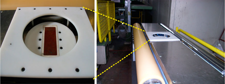
At a later point, the early prototype that was substituted by an inline measuring system based on the complete 3MA technique, i.e., besides IP also BN, HA, and EC were implemented in the system. The use of EMAT sensors for measuring deep-drawing parameters was no longer necessary. Based on the 3MA technique, an online testing system for the continuous determination of tensile strength (Rm), yield strength (Rp0.2), and other mechanical–technological characteristics in a broad range of steel grades was developed. The 3MA probe head is integrated into a movable, rotatable holder (see following Figure). The orientation between the main magnetic field and the rolling direction of the strip can be adjusted to 0°, 45°and 90°, which offers the possibility of determining the anisotropy parameters rm and Dr from the 3MA measurements.

Rotatable 3MA probe head holder and table carrier of the 3MA inline strip testing system
Again, the probe holder is mounted onto a hydraulically adjustable table carrier, which was equipped with distance rollers. A fast lowering of the entire construction in the case of an escape warning is necessary to avoid damaging the probe due to weld seams or zinc deposits on the strip. The external electronic equipment that is integrated into the measuring cabin controls the measuring procedure. The electronic equipment mainly consists of the 3MA measuring module, the electro-pneumatic device control, interfaces to supporting signals, like weld seam recognition, meter pulse, or strip velocity signals, and interfaces to the plant process control (PCS) and data management (DMS) systems of the strip steel production line.
For calibration, about 11,000 strips from 12 different steel grades were used. In contrast to the first IP+EMAT equipment described above, here it was not necessary to develop individual calibrations for each steel grade. Rather, it was found that the 12 steel grades could be combined into only four calibration classes, which are shown in Table below.
Table. Steel grade classes and calibration results.
|
Steel Grade Class |
RMSE of Rm [MPa] |
RMSE of Rp0.2 [MPa] |
No. of Strips |
|
IF, conventional |
5.4 |
8.2 |
2667 |
|
IF, high strength |
11.3 |
12.3 |
7764 |
|
Bakehardening |
5.8 |
8.8 |
1294 |
|
Structural |
7.9 |
10.1 |
164 |
Besides standard steel qualities (normal steel and construction steel), interstitial-free (IF) steel, and high strength material were investigated. The 3MA data that were determined at the beginning and at the end of the strip were associated to the destructively determined data of Rm and Rp0.2 data in order to determine the calibration functions. Table above also shows the results of this calibration in terms of the RMSE of the correlation between the 3MA data and destructive data.

|

|
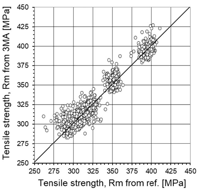
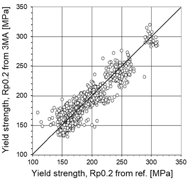
Results of the verification of the calibration; comparison of the values from 3MA measurements with destructively measured values: (a) for tensile strength, Rm and (b) for yield strength, Rp0.2.
In order to verify the calibration, i.e., to check the quality of the developed calibration functions and to evaluate the measurement accuracy of this 3MA application, a series of comparing measurements was carried out with the calibrated 3MA system. The nondestructively (nd) determined values of Rm and Rp0.2 were compared with the values that were measured from destructive (d) tensile tests at over 2700 strips. The diagrams of Figure below show the results of this comparison. The data from all four steel grade classes are combined in these diagrams.
In order to evaluate the deviation between nondestructive(nd) data and destructive(d) data, the RMSE values for the four steel grade classes are shown in Table below.
Table. Steel grade classes and results of verification measurements for Rm and Rp0.2
|
Steel Grade Class |
RMSE of Rm [MPa] |
RMSE of Rp0.2 [MPa] |
No. of Strips |
|
IF, conventional |
5.3 |
7.4 |
1985 |
|
IF, high strength |
6.8 |
9.3 |
68 |
|
Bakehardening |
11.2 |
15.6 |
55 |
|
Structural |
7.5 |
12.1 |
34 |
According to the rules of error propagation, the measuring uncertainties of both methods (nd and d) will contribute to the RMSE, i.e.,
where und and ud are the uncertainties of the nondestructive measurement and of the destructive measurement, respectively. The values of the RMSE, as shown in above Table, are close to the known measuring uncertainties of the destructive tensile test, indicating that the measuring uncertainty of 3MA is in the same range.
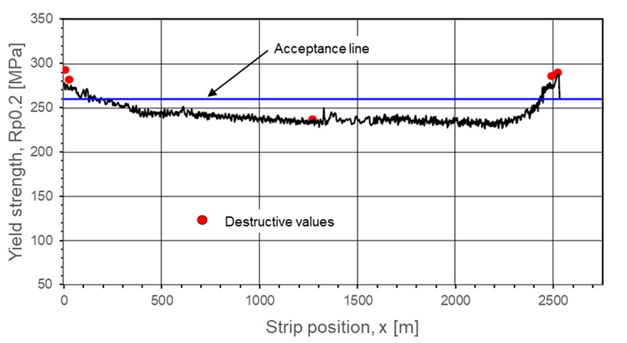
Inline measurements of Rm and Rp0.2 with 3MA can be used in order to precisely determine the acceptance range of a coil, as is shown in Figure below. The threshold level (acceptance line) of 260 MPa is not exceeded in the strip position range x > 200 m and x < 2400 m.

Inline measurement of yield strength Rp0.2 in a coil of 2500 m in length; destructive measurements of Rp0.2 at the beginning, at the end and in the middle of the strip are also shown as red dots; the acceptance line indicating the threshold level of Rp0.2 = 260 MPa is shown.
For more information, please contact LAB GAGES, or go on to visit our 3MA series Nondestructive Testing Systems Product Center.

311,Building 5,No.81,Meiyue Road,Waigaoqiao Free Trade Zone,Pudong,Shanghai,China
amy@labgages.com
021-50473900


About LAB | Cooperative Brand | Contact us | Sitemap

滬公網(wǎng)安備 31011502000213號

 滬ICP備12021537號-1
©2012-2024 LAB GAGES